Differential Communication Control Node: Solving Synchronised Multi-Unit Control
Written by Zak Tresh, Founder & Electronic Engineer, ZTPrototypes · Published 8 June 2026
This receiver module was part of a larger sporting event system with several LED indicator units spread around the venue. Every unit needed to follow the central scoring system at the same time, over long cable runs and in an electrically noisy environment. Our job was to make that wired control link reliable at each node.
The Challenge
We ruled out wireless for this part of the system because the link needed predictable latency and strong noise immunity in a crowded venue. A wired differential bus gave us that, but it also meant the receiver design and PCB layout had to be planned around EMC from the start.
Long cable runs pick up interference, especially when they sit near other electronics and power equipment. If the differential receiver or termination is wrong, the failure can be much more visible than an occasional corrupted packet. A unit can fall out of sync or flicker in front of everyone watching.
The electrical environment made this harder than the bench version of the problem. Live venues can have dimmer packs, motor drives and other equipment putting noise onto shared power and ground paths. The number of nodes could also change from one installation to another, so the link had to stay stable with a short bus and a few receivers as well as a longer, fully populated network.
Our Approach
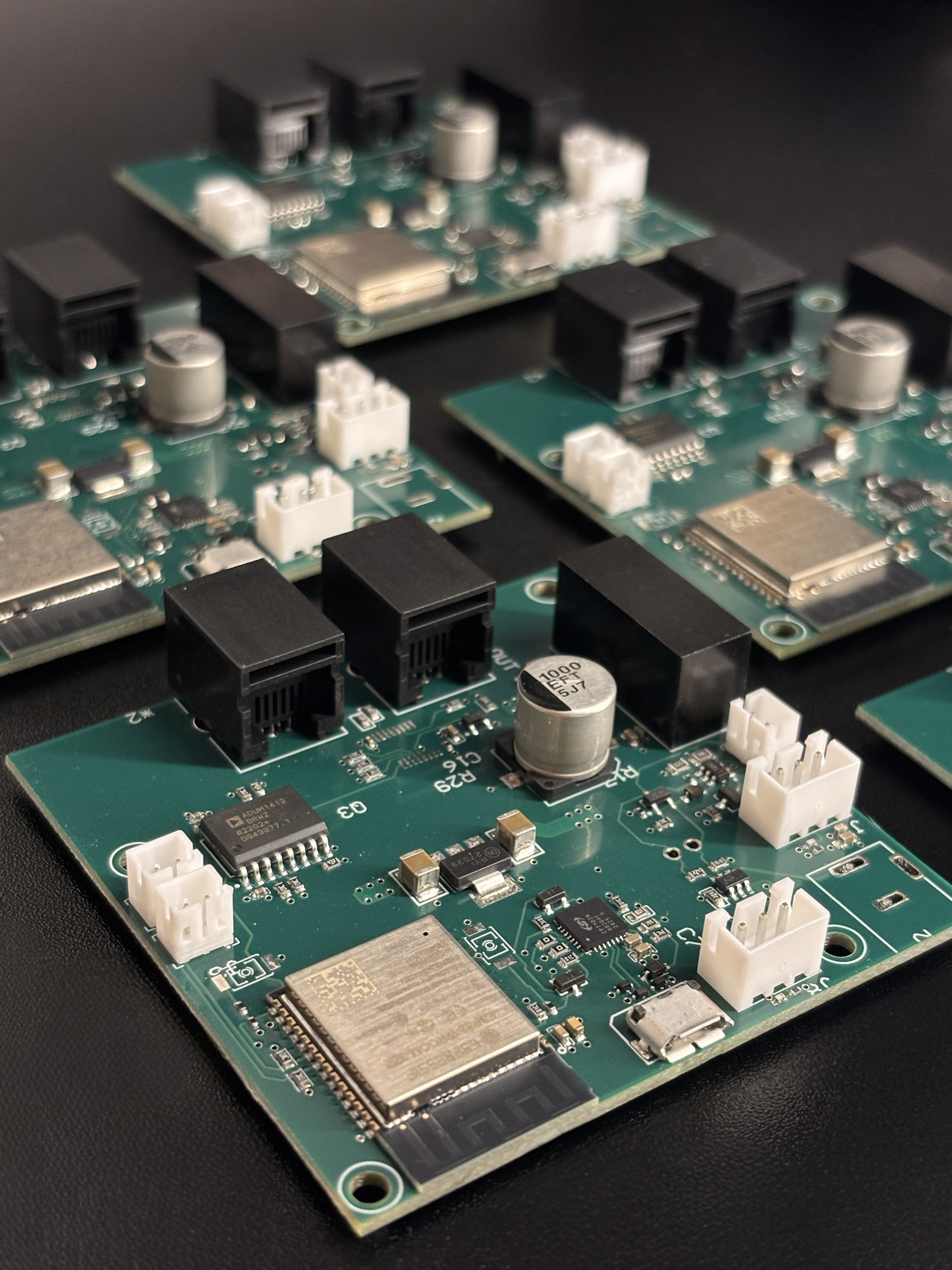
We built the receiver around a differential communication standard and treated EMC as part of the PCB layout, with the routing, termination and grounding chosen for the actual venue environment. We wanted the first board to behave properly on site, so those decisions were made before routing rather than added as fixes after testing.
The differential pairs were routed with controlled spacing and matched lengths, and we placed termination where the bus topology required it to limit reflections. We also kept the grounding organised around a single reference path so noise currents from one unit were less likely to move through another unit's signal reference.
Because the same receiver had to work in a multi-node network, we tested it at both ends of the expected system size. We started with a minimal setup, then loaded the bus with the full number of units and checked that adding nodes did not introduce timing drift, flicker or new noise problems.
We then injected electrical noise deliberately at levels representative of the venue. That test exposed a marginal grounding issue that the quiet bench setup had not shown. We corrected it before sign-off and repeated the noise testing until the receiver stayed stable under the interference we expected on site.
Outcome
The finished receiver modules keep the LED units synchronised with no visible timing drift or flicker during extended testing in a noisy electrical environment. The result came from treating EMC as a layout requirement from the first revision and then testing the board under conditions that were deliberately worse than a normal lab bench.
What This Demonstrates
EMC work is often invisible when it is done properly. A differential link can look perfect on a short cable in a quiet lab and then fail intermittently beside motors, lighting controllers or long cable runs. Once that happens, the fix may require a new PCB rather than a configuration change, so we put the noise immunity into the routing, termination and grounding before the first board was built.
The same problem appears in industrial control systems and distributed sensor networks. As the number of nodes and cable length increase, the electrical environment becomes part of the communication design. A link that works point to point still has to be proven when the full network is connected.
The deliberate noise injection testing on this project is worth calling out as a general principle, not just a detail specific to this build. Most EMC problems in the field trace back to a design that was only ever validated somewhere quieter than where it actually operates. Building a repeatable way to inject representative interference and confirm a design holds up under it, rather than trusting a clean lab result as proof of reliability, is what separates a communication system that's actually field-ready from one that only looks it. It's a step we build into any EMC-sensitive design [links to: /services/emc-compliance] regardless of the application.
Working with a noisy or multi-node system?
A Validation Sprint identifies EMC and communication risk before it becomes an expensive problem discovered late in a build, when a layout fix means a full board respin rather than a straightforward adjustment.
Explore the Validation Sprint